|
Please note that all of the small pictures shown in this article are
backed up by larger images so that you can get a better look at the
details if you so desire. Just click on any of the small pictures to
look at the larger version. When done looking at the larger picture,
just hit the "Back" button on your browser to return to the main article.
Building this project requires the use of tools that are capable of serious injury to you. If you attempt to build this project or something similar be sure you wear safety glasses and use all necessary safety precautions. If you are not familiar with the use of the tools required, obtain assistance from someone who is familiar with their proper use.
Project Background & Goals
I looked around on the web and found a couple of different designs that helped me get started. After building two different versions of the loop I came up with something that worked. It was a copper loop antenna with a capacitive fed gamma match. I had to rebuild the gamma match several times to get something that worked. I liked the way the antenna worked so I built a second one and stacked them for some additional gain using a phasing harness with impedance matching. They seemed to work pretty well but the harness and antennas were pretty flimsy. I had to disassemble the system several times due to a house move and a home construction project. I found that each time I had to touch the set up, something would go wrong. That is why I decided to try to build something that was a little more reliable. The antenna I show here is my third generation design. The goal for this next design was to build something that I could get a good SWR response. I also wanted a design that allowed for adjustment. And and third goal was easy construction using parts available from the local hardware supply. I wanted good mechanical reliability and a minimum of metal support components that might affect the response of the antenna. As a result of these goals I had to play around with the design until I found something that gave me a good SWR match. It took me a little longer, but now I have a design that I think will work well. |
Mast Selection & Mounting Bracket
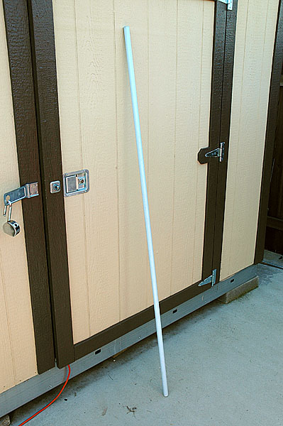 I decided to mount the antenna to a fiberglass mast that would eventually be mounted
on top of a metal push-up mast. The fiberglass mast I selected is a 1 inch rod that is
72 inches long. I was able to find the rod at my local TAP Plastics store.
The price was really more than I wanted to pay but I figured it would last a long
time. The fiberglass mast I purchased is shown in the image to the left of this text.
Click on the image to see a larger picture.
I decided to mount the antenna to a fiberglass mast that would eventually be mounted
on top of a metal push-up mast. The fiberglass mast I selected is a 1 inch rod that is
72 inches long. I was able to find the rod at my local TAP Plastics store.
The price was really more than I wanted to pay but I figured it would last a long
time. The fiberglass mast I purchased is shown in the image to the left of this text.
Click on the image to see a larger picture.
The next thing to consider was how to mount the fiberglass mast to the top of the metal push-up mast. I decided to make a plate with holes drilled in it to allow the bottom of the fiberglass mast to be bolted to one side of the plate and the top of the metal mast to be bolted to the other side of the plate. I used U-bolts to secure the masts to the metal plate, two U-bolts for the fiberglass mast and two for the metal mast. The fist picture below is a picture of the metal plate marked and ready to drill. The second picture is the plate after the holes have been drilled. The plate is aluminum that is 3/16" thick and 3" wide x 10-1/2" long.
You will notice three other items in the second picture besides the metal plate. There is a U-bolt that is one of four that will be used to secure the two masts to the plate. Also there is a PVC coupler section that is normally used for PVC plumbing. I cut one of these couplers into four semi circle sections to act as a spacing shims between the U-bolts and the fiberglass mast. I split the coupler length-wise with a hack saw and then cut each half section in half across the circumference to give me the four separate pieces. One thing to note is that the coupler has a ridge on the interior surface that you will need to avoid or you will end up having to file it off later. Of course you don't have to use the shim at all if you prefer not to. I wanted to use a shim so that the diameter of the fiberglass mast matched more precisely with the diameter of the U-bolts. I also wanted to avoid cutting into the fiberglass mast with the U-bolt when it was tightened down.
In this picture you can see the completed mast plate attached to bottom of the fiberglass mast. Notice the two PVC shims installed between mast and the U-bolts. One of the shims was seen in the previous picture prior to installation. Installation of the shims is not absolutely necessary but it is a nice touch that gives the mast a more secure fit to the U-bolts. |
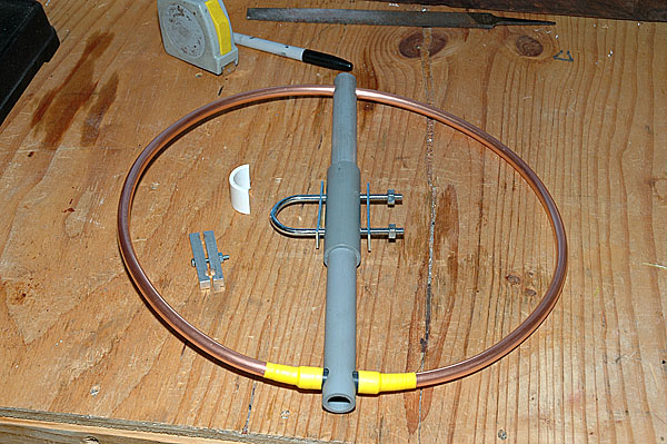
Antenna Materials

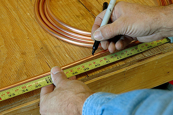
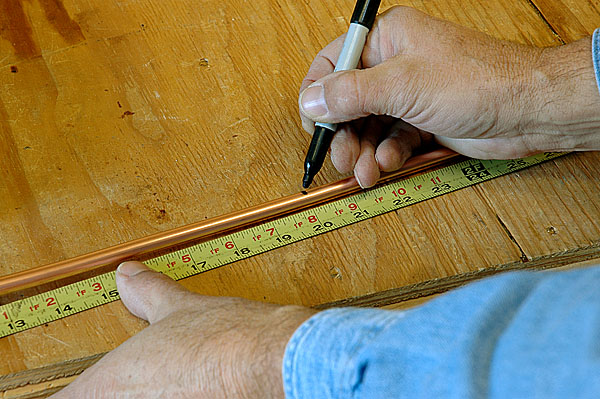
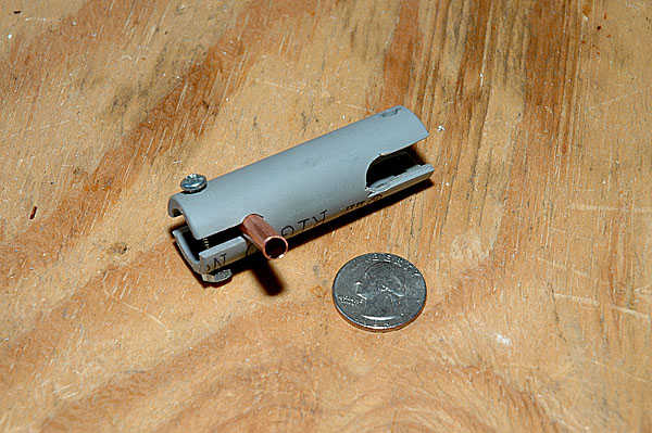
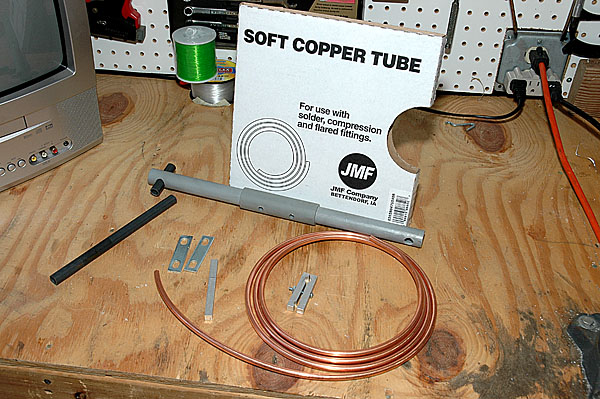 The first picture shows the copper tube that was used for the radiating element of the
antenna. It is 3/8" outside diameter soft copper. The second picture shows the copper that
was used to make the gamma match tube. The copper tube used for the gamma match is 1/4"
outside diameter. Also shown in the picture is a completed cross boom, the completed
gamma tube clamp, and two metal plates that came off the U-bolts. These plates were not
needed for clamping the mast to the mast plate. However they will be used for clamping
the antenna boom to the mast later in the assembly. A piece of the plastic tube that I
used for the radiating element separator is also shown.
The first picture shows the copper tube that was used for the radiating element of the
antenna. It is 3/8" outside diameter soft copper. The second picture shows the copper that
was used to make the gamma match tube. The copper tube used for the gamma match is 1/4"
outside diameter. Also shown in the picture is a completed cross boom, the completed
gamma tube clamp, and two metal plates that came off the U-bolts. These plates were not
needed for clamping the mast to the mast plate. However they will be used for clamping
the antenna boom to the mast later in the assembly. A piece of the plastic tube that I
used for the radiating element separator is also shown.
|
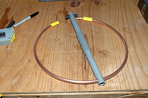
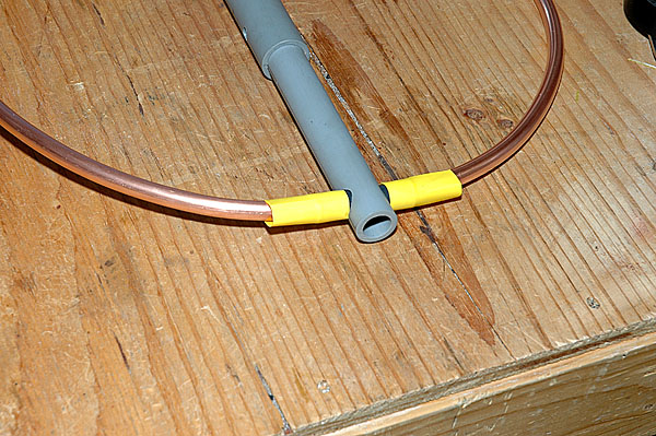
Antenna Construction Details
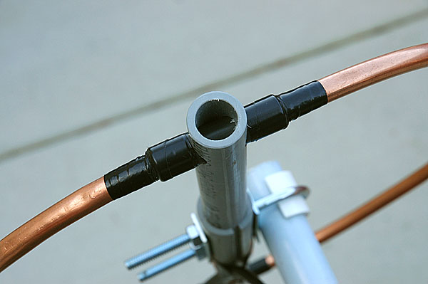
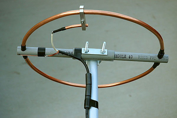
 The first item that I will describe is the boom. This is used to secure the antenna to the
mast. It also holds the two ends of the antenna loop apart. The boom is made out of schedule
40 PVC electrical conduit. This material is good because it is an insulator and is also
made to be UV light resistant. It is also easy to work with. I used 1/2" conduit for the
boom and 3/4" to beef up the center section of the boom where it will be bolted to the
mast. 1/2" conduit will not normally fit into 3/4" conduit so I split the 3/4" conduit down one
side by cutting it with a hack saw. This allowed me to force the 1/2" conduit into the split
3/4" conduit. You can see the widened split in the 3/4" section in the enlarged picture. The
boom is 14-1/2" long and the center 3/4" section is 4" long. To install the split 3/4" conduit
over the 1/2" conduit I drove the 1/2" boom into the 3/4" section with a rubber mallet until
the 3/4" section was on the 1/2" section. Then I used a deep socket wrench socket that was
lager enough to fit over the 1/2" section but not large enough to fit over the 3/4" section
to further drive the 3/4" section toward the center of the boom. I finished driving the 3/4"
section to the center of the boom by placing the 1/2" section in a vice that was not
tightened down on 1/2" section but was closed enough so that it would not allow the 3/4"
section to pass by the vice jaws. That way I was able to complete driving the 3/4" section to
the middle of the boom by tapping on the end of the 1/2" boom with the rubber mallet. Once
that was done I drilled the necessary holes. Two in the center for the U-bolt to go through
and one at each end of the boom that are larger. One hole for the radiating element and one
slightly larger hole on the other end for the spreader. The spreader is a piece of PVC that I
happened to have on hand. It had an inner diameter that was large enough so that the 3/8" copper
radiating element could be inserted into it. The spreader is 2" long and the radiating
element is inserted 1/4" into it so that the two ends of the copper loop are separated by 1-1/2".
The first item that I will describe is the boom. This is used to secure the antenna to the
mast. It also holds the two ends of the antenna loop apart. The boom is made out of schedule
40 PVC electrical conduit. This material is good because it is an insulator and is also
made to be UV light resistant. It is also easy to work with. I used 1/2" conduit for the
boom and 3/4" to beef up the center section of the boom where it will be bolted to the
mast. 1/2" conduit will not normally fit into 3/4" conduit so I split the 3/4" conduit down one
side by cutting it with a hack saw. This allowed me to force the 1/2" conduit into the split
3/4" conduit. You can see the widened split in the 3/4" section in the enlarged picture. The
boom is 14-1/2" long and the center 3/4" section is 4" long. To install the split 3/4" conduit
over the 1/2" conduit I drove the 1/2" boom into the 3/4" section with a rubber mallet until
the 3/4" section was on the 1/2" section. Then I used a deep socket wrench socket that was
lager enough to fit over the 1/2" section but not large enough to fit over the 3/4" section
to further drive the 3/4" section toward the center of the boom. I finished driving the 3/4"
section to the center of the boom by placing the 1/2" section in a vice that was not
tightened down on 1/2" section but was closed enough so that it would not allow the 3/4"
section to pass by the vice jaws. That way I was able to complete driving the 3/4" section to
the middle of the boom by tapping on the end of the 1/2" boom with the rubber mallet. Once
that was done I drilled the necessary holes. Two in the center for the U-bolt to go through
and one at each end of the boom that are larger. One hole for the radiating element and one
slightly larger hole on the other end for the spreader. The spreader is a piece of PVC that I
happened to have on hand. It had an inner diameter that was large enough so that the 3/8" copper
radiating element could be inserted into it. The spreader is 2" long and the radiating
element is inserted 1/4" into it so that the two ends of the copper loop are separated by 1-1/2".
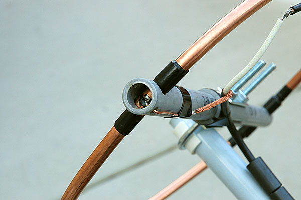
The next item is the gamma clamp which is also shown in the picture. This is used to clamp the gamma tube to the radiating element as well as have the ability to be moved. The ability to move the clamp allows you to to move the feed point on the radiating element as well as vary the capacitance of the gamma tube. The clamp was made out of 5/16" aluminum square stock that I just happened to already have. A hole is drilled through the center of each piece to allow a screw to be used to clamp the two bars together. I also drilled two different diameter arcs near the end of each section. I used two different drill sizes to match the radius of the two different copper tube diameters. The arcs are not complete semi-circles because I wanted the two bars to be able to clamp to the copper tubes without touching each other. That way I could ensure a tight fit once the clamp is tightened down. The way I accomplished this was to put a spacer between the two bars of metal and clamp them together prior to drilling. I then drilled a hole in the center of the spacer which left an arc cut into each metal clamp bar.
Other things to notice about the feed line. #1 notice that the shield on the feed line is soldered to a ground wire that connects to the loop. This allows some flexibility provided by the braided shield so that the gamma coax can be moved in and out of the gamma tube for adjustment. It also allows for easy rework of the ground connection if needed. The ground wire only has to be soldered to the loop one time. You can still unsolder the feed line from the ground wire if needed. Soldering anything to the loop requires a lot of heat, so if you can minimize the number of times needed to do this you are better off. This method requires that you only have to solder to the radiating element once. #2 notice that I used several toroid cores on the feed line. You can see them resting against the mast. This was done to enhance the operation of the antenna system by preventing the signal radiating from the antenna from flowing back down the shield of the feed line. In the picture you can also see the metal plate on the center section of the boom. This metal plate came with the U-bolt and is there just to enhance the strength of the boom when the U-bolt is tightened down. There is also a metal plate on the other side of the boom. I had extra metal plates from the U-bolts used to attach the fiberglass mast to the mast mounting plate.
|
SWR Measurement
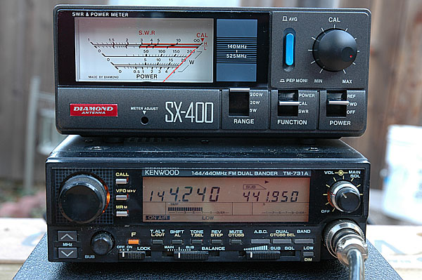
 These two pictures show the SWR calibration and measurement of the antenna. The
first picture on the left shows the meter once it was calibrated to the power level
of the transmitter. I used the low power setting on the radio. The power level
being transmitted can be seen just below the two meter frequency readout on the
left side of the display. I used 144.240 MHz rather than 144.250 MHz as my tune
frequency because 144.250 MHz is sometimes used as a net frequency in my area and
I did not want to interfere with possible activity. Also note that this radio is
an FM only radio while the intended use of the antenna is for SSB. Notice that the
needle on the meter is fully deflected to the "CAL" position on the right side of
the meter and the center switch on the meter is set to the "CAL" position.
These two pictures show the SWR calibration and measurement of the antenna. The
first picture on the left shows the meter once it was calibrated to the power level
of the transmitter. I used the low power setting on the radio. The power level
being transmitted can be seen just below the two meter frequency readout on the
left side of the display. I used 144.240 MHz rather than 144.250 MHz as my tune
frequency because 144.250 MHz is sometimes used as a net frequency in my area and
I did not want to interfere with possible activity. Also note that this radio is
an FM only radio while the intended use of the antenna is for SSB. Notice that the
needle on the meter is fully deflected to the "CAL" position on the right side of
the meter and the center switch on the meter is set to the "CAL" position.
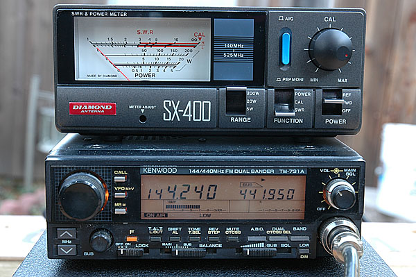
The second picture on the right shows the actual SWR measurement. Notice that the center switch is now set to the "SWR" position. The radio is transmitting as seen on the power level display below the frequency readout. Once the antenna was in it's final adjusted state the SWR measurement barely moved off of the 1:1 measurement position. |
|
Future Plans
My intention is to build a second antenna to be used in a stacked loop configuration. Adding a second antenna will require the building of a phasing harness to split the signal between the two antennas. |
© Michael Fedler, 2007