|
Please note that all of the small pictures shown in this article are
backed up by larger images so that you can get a better look at the
details if you so desire. Just click on any of the small pictures to
look at the larger version. When done looking at the larger picture,
just hit the "Back" button on your browser to return to the main article.
Building this project requires the use of tools that are capable of serious injury to you. If you attempt to build this project or something similar be sure you wear safety glasses and use all necessary safety precautions. If you are not familiar with the use of the tools required, obtain assistance from someone who is familiar with their proper use.
Tools
Project Background & Goals
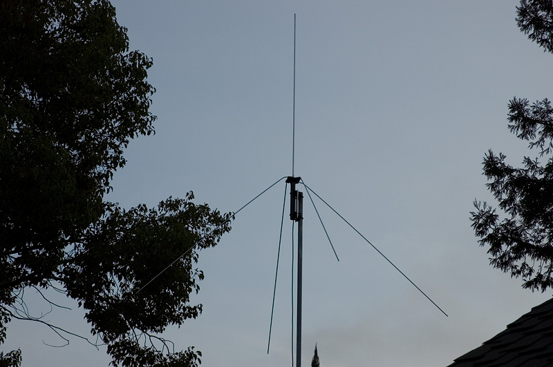
For single side band it is really best to have a horizontally polarized antenna which this antenna is not. Using an antenna that is crossed polarized from other stations in your area results in about a 20 dB loss in signal strength. If the band is open and you are receiving signals that are bouncing off the ionosphere then polarization is not so important since the polarization tends to get mixed up. Another consideration is that the radiation angle for a quarter wave antenna is pretty high and will not be as good for DX signals as compared to an antenna the has a lower angle of radiation. At some point I will build something else that is better suited for sideband, but for now having an antenna that is vertically polarized is better than nothing on sideband. Another consideration was the gain of the antenna. I wanted something that was small and relatively easy to build. I was not as concerned about putting out the most potent signal. Since this is a quarter wave antenna it is considered a unity gain antenna as compared to a dipole "0 dBd". Quarter wave antennas are pretty simple and do not require any matching circuitry when fed with standard 50 ohm coax. A couple more considerations were materials and level of mechanical complexity. I wanted a design that was fairly simple but mechanically strong enough to stand up to the weather. I live in a relatively moderate climate so I did not have to worry about snow or ice loading. The design just had to stand up to rain and wind. I knew that I wanted to make the radials out of aluminum rod but other than that my design was open to whatever material I could find. |
Mast Mounting Materials
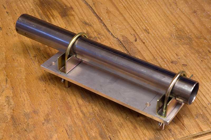
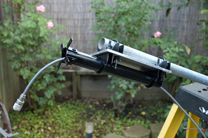
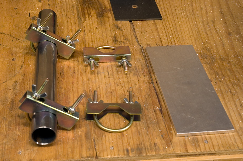 I knew that I wanted the antenna mount to be fairly strong so I chose my materials with
that in mind. At a local metal supply house I found a length of steel tubing and some
U-bolts with brackets that would work great for the main mounting components. The steel
tube which the antenna will be mounted to is 1-3/8" in diameter and 12" long. The U-bolts
and brackets were originally made for some other type of antenna system and were being sold
as surplus. Standard U-bolts would also work for this project but these surplus brackets
were cheaper and came with additional brackets to center the mast sections. Also shown in
this picture is a piece of 1/4" aluminum plate that will be used to bolt the mast to the
antenna mounting tube. I already had the 1/4" plate material that I cut off of a larger
piece of aluminum sheet.
I knew that I wanted the antenna mount to be fairly strong so I chose my materials with
that in mind. At a local metal supply house I found a length of steel tubing and some
U-bolts with brackets that would work great for the main mounting components. The steel
tube which the antenna will be mounted to is 1-3/8" in diameter and 12" long. The U-bolts
and brackets were originally made for some other type of antenna system and were being sold
as surplus. Standard U-bolts would also work for this project but these surplus brackets
were cheaper and came with additional brackets to center the mast sections. Also shown in
this picture is a piece of 1/4" aluminum plate that will be used to bolt the mast to the
antenna mounting tube. I already had the 1/4" plate material that I cut off of a larger
piece of aluminum sheet.
|
Additional Mounting Materials
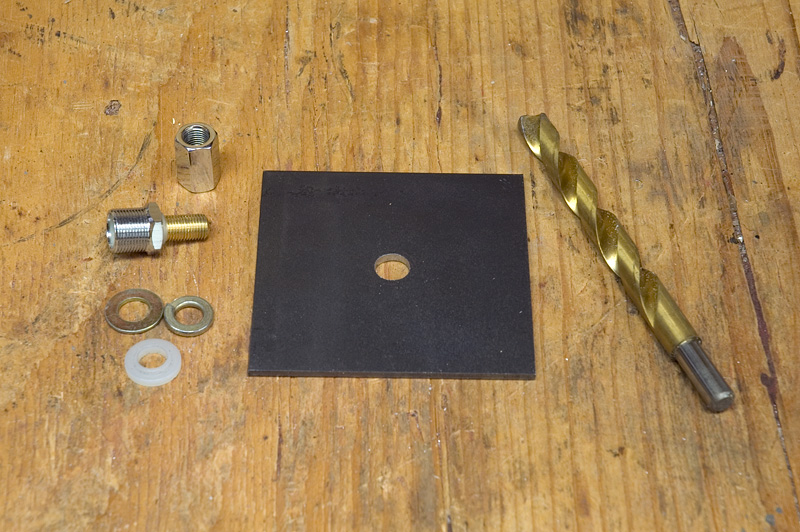
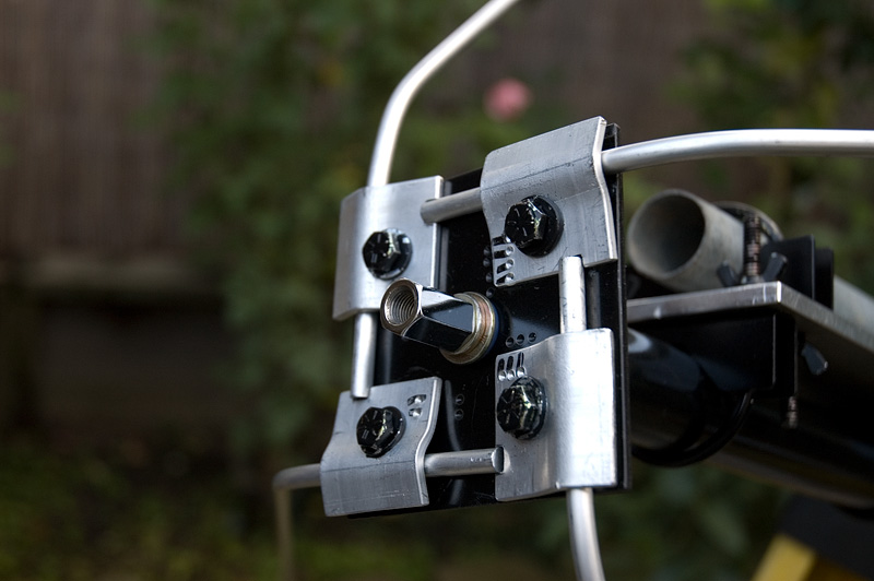
 The square piece of metal in the first photo is the plate that the antenna radiating element
will be mounted on. This piece is 1/8" thick steel that is 4" by 4" square. As you can see
in the picture, I had already drilled a hole in the center of the plate to mount the feed point
hardware in. The feed point hardware shown in the photo is standard hardware that can be
purchased from any radio supply company. It accepts a 3/8" x 24 thread size antenna element
on one side and is fitted with a standard SO-259 connector on the other side to plug in your
PL-259 coax connector.
The square piece of metal in the first photo is the plate that the antenna radiating element
will be mounted on. This piece is 1/8" thick steel that is 4" by 4" square. As you can see
in the picture, I had already drilled a hole in the center of the plate to mount the feed point
hardware in. The feed point hardware shown in the photo is standard hardware that can be
purchased from any radio supply company. It accepts a 3/8" x 24 thread size antenna element
on one side and is fitted with a standard SO-259 connector on the other side to plug in your
PL-259 coax connector.
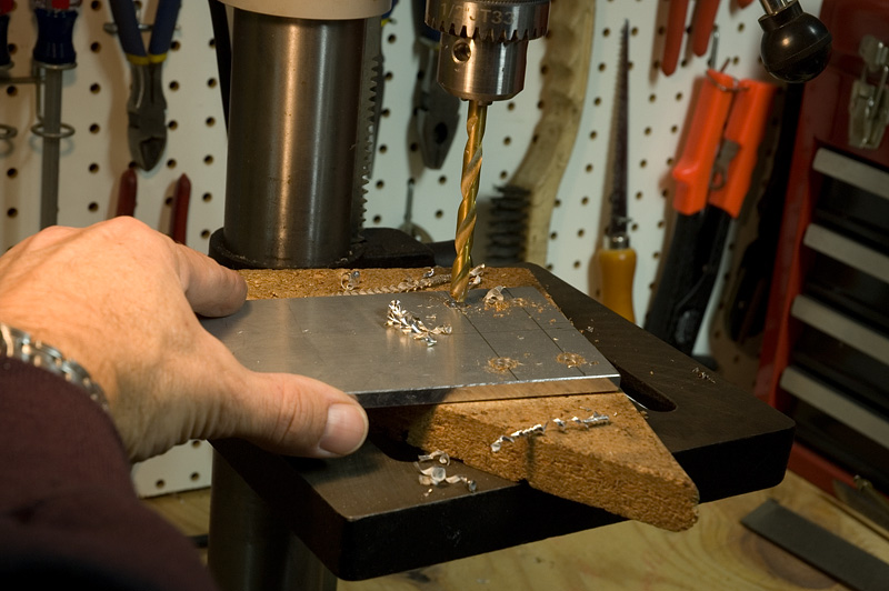
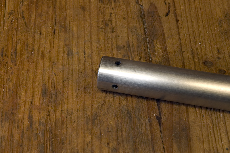
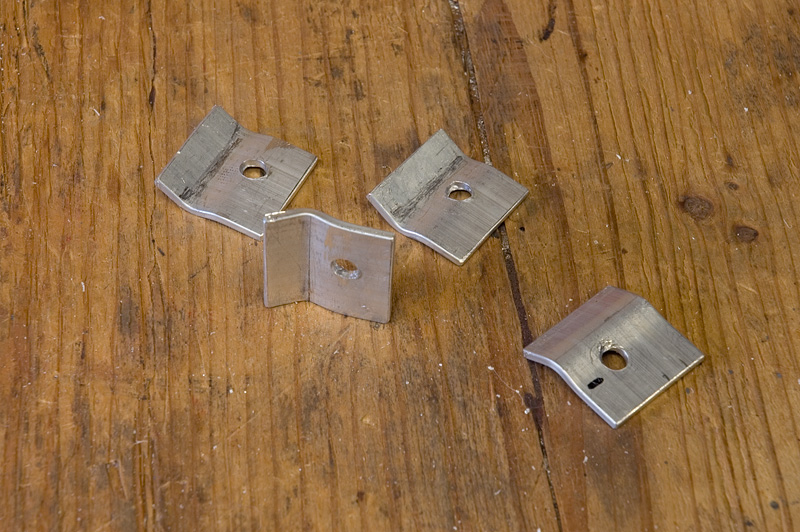
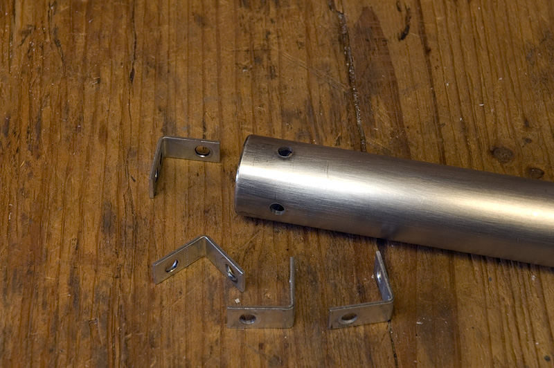
Notice that the feed point hardware shown in the first photo has two plastic insulators (one already on the bolt portion of the SO-239 and another separate one). These are used to keep the radiating element connections isolated from the rest of the grounding structure. The center (threaded brass) portion of the feed point hardware will attach to the radiating element while the body of the SO-239 will be in contact with the ground portion of the hardware. The second photo shows a close up view of the mounting tube along with four right angle mounting brackets. The right angle brackets will be attached to the mounting tube and will eventually support the top plate. As you can see in the picture I have already drilled the four holes in the mounting tube where the right angle brackets will be attached. |
|
Antenna Materials
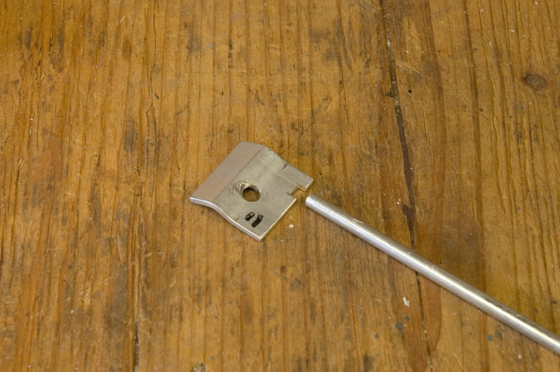
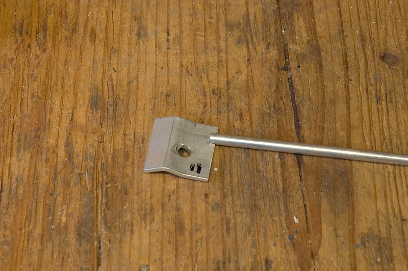
The material used for the actual antenna radiator and ground radials is aluminum rod. I used 1/4" diameter rod for the ground radials and 3/8" aluminum rod for the radiating element. I chose 3/8" rod for the radiating element so that I could thread one end of it and then screw it into the standard feed point hardware that I had already purchased. The only other hardware needed were some clamp brackets to hold the ground radials in place. I decided to make the radial clamps out of 1/8" thick 1-1/2" aluminum that I already had on hand. |
Antenna Construction Details
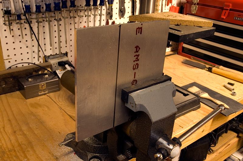
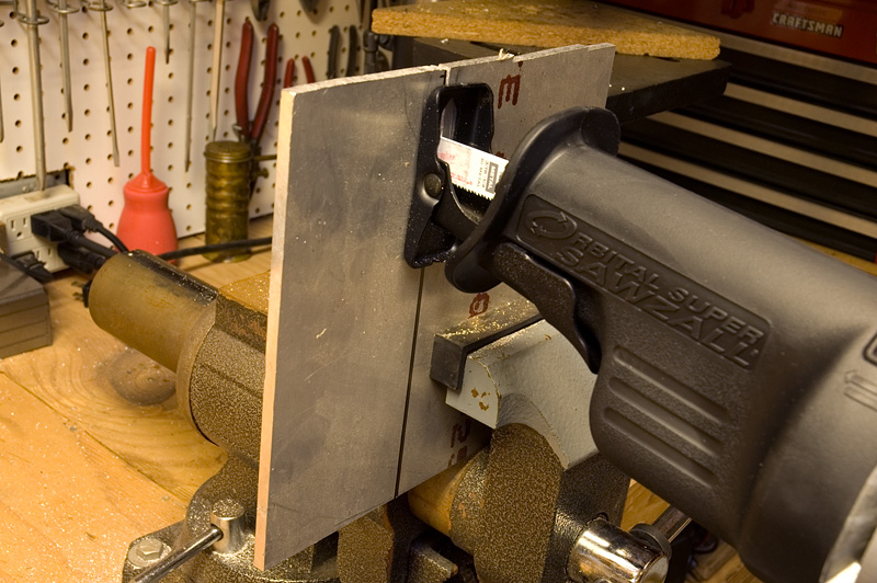
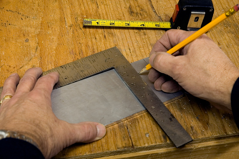
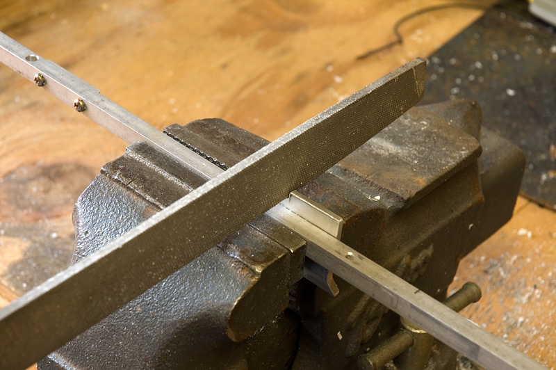
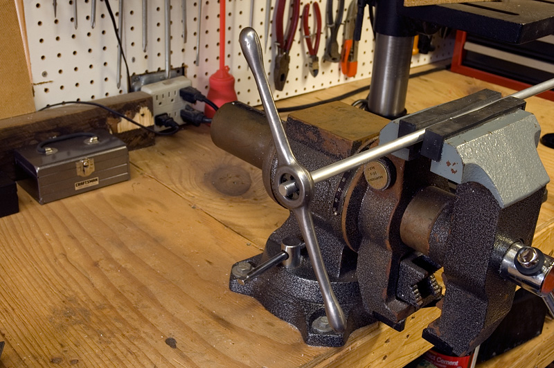
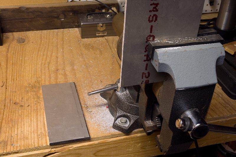 The first item to fabricate was the mast mounting plate. The first photo shows the raw aluminum
plate that I used. In the second photo I am cutting the plate to size with a reciprocating saw.
The third photo shows the mast plate after is has been cut to size (3-1/2" x 8-1/2"). Before moving on to the
next step it is a good idea to use a file on the edges of the mast plate to remove any rough
edges that could cut you. I generally just file all edges at a 45 degree angle.
The first item to fabricate was the mast mounting plate. The first photo shows the raw aluminum
plate that I used. In the second photo I am cutting the plate to size with a reciprocating saw.
The third photo shows the mast plate after is has been cut to size (3-1/2" x 8-1/2"). Before moving on to the
next step it is a good idea to use a file on the edges of the mast plate to remove any rough
edges that could cut you. I generally just file all edges at a 45 degree angle.
|