Preparation
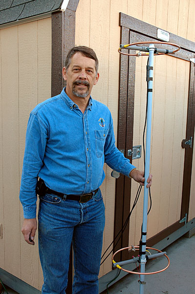
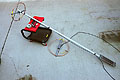 There wasn't too much preparation needed for this project. Just gathering the parts to
be assembled along with a few tools and something to hold the antennas off the ground
while I worked on them. In this picture you can see that I have the first antenna that
has already been installed on the fiberglass mast as will as the second antenna which
is not yet installed. Please note that each antenna has a separate coax feed line
attached to it. That is not really needed at this stage but I had already attached a
feed line to each antenna for SWR adjustment. Once both antennas are mounted a phasing
harness will be built to connect the antennas to a single feed line.
There wasn't too much preparation needed for this project. Just gathering the parts to
be assembled along with a few tools and something to hold the antennas off the ground
while I worked on them. In this picture you can see that I have the first antenna that
has already been installed on the fiberglass mast as will as the second antenna which
is not yet installed. Please note that each antenna has a separate coax feed line
attached to it. That is not really needed at this stage but I had already attached a
feed line to each antenna for SWR adjustment. Once both antennas are mounted a phasing
harness will be built to connect the antennas to a single feed line.
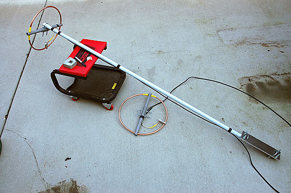
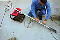 In this picture you can see me marking the location where the clamp for the second
antenna boom will be installed. The distance I chose for the antenna separation was
48". I measured from the clamp on the top antenna down the mast 48" and marked it with
a marker pen. You can see the spacer shim that will be used between the U-bolt and
the mast sitting on the red seat of the mechanics cart. It is the small semi-circular
piece of white PVC. This was made previously for use at this time.
In this picture you can see me marking the location where the clamp for the second
antenna boom will be installed. The distance I chose for the antenna separation was
48". I measured from the clamp on the top antenna down the mast 48" and marked it with
a marker pen. You can see the spacer shim that will be used between the U-bolt and
the mast sitting on the red seat of the mechanics cart. It is the small semi-circular
piece of white PVC. This was made previously for use at this time.
Second Loop Installation
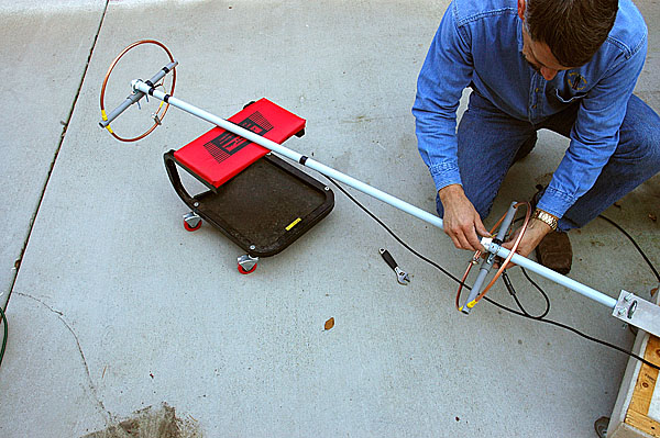
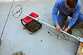 Now that the location for the second loop has been marked, the installation can begin.
All that was needed was to put the U-bolt and shim around the mast then to insert the
U-bolt through the boom. That is what is being shown in this picture. After the
components are in place, tighten down the nuts on the U-bolt. Note that both antennas
need to be positioned with the same orientation. That means that both booms needs to
be parallel to each other rotationally. If you were to look down from the top of the
mast, both booms should line up exactly. Also the side of the antenna that was chosen
for the top of the first antenna should be chosen as the top on the second antenna.
This is important so that both antennas radiate with the same pattern. This is another
good reason why both antennas should be built exactly the same. They should be twins.
Once everything is lined up, tighten down the U-bolt nuts and the installation of the
second antenna is complete.
Now that the location for the second loop has been marked, the installation can begin.
All that was needed was to put the U-bolt and shim around the mast then to insert the
U-bolt through the boom. That is what is being shown in this picture. After the
components are in place, tighten down the nuts on the U-bolt. Note that both antennas
need to be positioned with the same orientation. That means that both booms needs to
be parallel to each other rotationally. If you were to look down from the top of the
mast, both booms should line up exactly. Also the side of the antenna that was chosen
for the top of the first antenna should be chosen as the top on the second antenna.
This is important so that both antennas radiate with the same pattern. This is another
good reason why both antennas should be built exactly the same. They should be twins.
Once everything is lined up, tighten down the U-bolt nuts and the installation of the
second antenna is complete.
Assembled & Ready For Harness
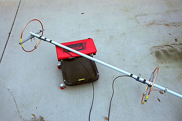
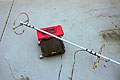 At this point you should be completed with the installation of the second loop on the
mast. This picture shows the completed assembly prior to building the phasing harness.
Note that the loops are both orientated in the same direction as described in the
previous paragraph. Also note that there are still two coax feed lines, one from each
antenna. These will be cut to length and combined once the phasing harness is built
and installed. I ran into a problem when installing the second antenna. The loop did
not want to sit exactly perpendicular to the mast. The way I solved this was to
attach a hose clamp to the mast and stretch a wire from that clamp to the ends of the
U-bolt. That allowed me to apply enough tension to secure the antenna in perpendicular
alignment. If my construction process had been better when I first built the boom, I
could have avoided this situation. You can also see in this picture how I have secured
the toroid cores to the mast using electrical tape. Now the only thing left is to build
the phasing harness.
At this point you should be completed with the installation of the second loop on the
mast. This picture shows the completed assembly prior to building the phasing harness.
Note that the loops are both orientated in the same direction as described in the
previous paragraph. Also note that there are still two coax feed lines, one from each
antenna. These will be cut to length and combined once the phasing harness is built
and installed. I ran into a problem when installing the second antenna. The loop did
not want to sit exactly perpendicular to the mast. The way I solved this was to
attach a hose clamp to the mast and stretch a wire from that clamp to the ends of the
U-bolt. That allowed me to apply enough tension to secure the antenna in perpendicular
alignment. If my construction process had been better when I first built the boom, I
could have avoided this situation. You can also see in this picture how I have secured
the toroid cores to the mast using electrical tape. Now the only thing left is to build
the phasing harness.